Main Street, City, State
Call Us For Free Consultation
Facebook | Twitter

NSW Interesting Tunnels

Sydney Harbor Tunnel, Sydney NSW
This tunnel runs along the sea bed, in a trench, under the Sydney Harbor, adjacent to the Sydney Harbor Bridge. This tunnel was constructed using preformed section, floated on barges into position, lowered and joined on the sea bed. Then the sea water was pumps out, the infrastructure was fitted, creating the road tunnel as you see it today. After construction the trench was filled in over the tunnel with river sand and permanently buried. The fire protection design in this tunnel was designed by others, using a unique design philosophy, see our "Interesting Tunnels" page for more details
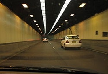
Sydney Harbor tunnel
Is a driver view whilst driving north through the Sydney Harbor Tunnel, on the right side of the pictured is the services corridor, where all the equipment is housed.
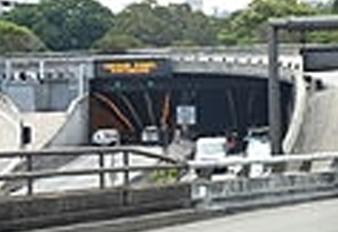
Sydney Harbor Tunnel Northern Portal Entrance
Is a view of the road tunnel portal from the North Sydney
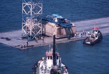
Sydney Harbor tunnel barge with tunnel section
Is a section of the road tunnel structure on the barge being position by tugs, prior to lowering into position.
Lane Cove Tunnel, Sydney NSW
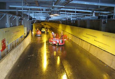
This tunnel is protected by a Deluge System & fire hydrants and Fire hose Reels, all feed from a ring main system. The water supply is from town's main grade 1 supply and booster pumps located at the Lane Cove End, located at ground levle above the tunnel. There is an underground pipe from the pump room via a services tunnel to the road tunnel below.This tunnel is unique as it has a 90 metre down gradient from the Lane Cove end down, creating many hydraulic issues, mainly over pressurization that had to be solved during design, by using 2 sets of inline pressure reducing valve stations ensure that over pressurization did not occur during normal & fire scenario operations.
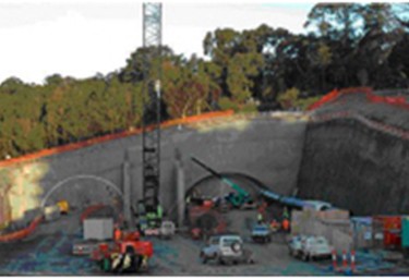
Lane Cover tunnel during construction
Lane Cove Road Tunnel, view from Epping end, during early construction view of the portal (left) and tunnel with shotcrete internal wall lining method
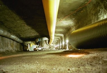
Lane Cover tunnel Epping Portal
During construction fresh air is supplied to the work face via a flexible the temporary supply air ducts (yellow flexible ducting) to provide fresh air to the excavation working face (right),
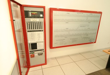
Lane Cover tunnel Fire Panel
Lane Cove Road Tunnel, view of the fire alarm panel and mimic panel, located in the control room, the controller console is to the left of this photo (see below for the controllers console)

Lane Cover tunnel control room
A view of the control room video wall and operators console (see left hand side the edge of the fire system minic panel red border object)
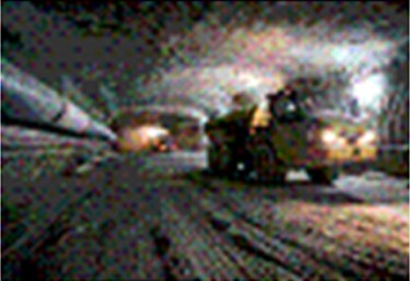
Lane Cover tunnel construction view
Lane Cove Road Tunnel, at early construction phase, showing one on the many underground earth moving trucks (we call them Moxys) removing the mined spoil, as you can see there is no concrete floor, just road base. In NSW all road tunnels do not a formed concrete shell, as the rock / limestone is capable of self-supporting (sorry about the poor picture quality). The infrastructure (lighting / deluge / jet fans) would be fitted once mining operations are completed.
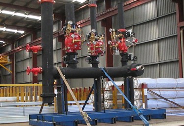
Lane Cover tunnel Deluge Control valve Manifold
Lane Cove Tunnel, view of one of the many deluge valve manifolds, this one pre built off site in the workshop, loaded on the delivery truck ready for site delivery/ installation
Lane Cover tunnel Construction view of deluge system
Lane Cove Road Tunnel Sydney NSW, showing the high level of the deluge piping system & nozzle locations, this photo was taken during the commissioning phase just prior to system activation.
Epping to Chatswood Rail Tunnel, Sydney NSW
This tunnel is protected by Fire Hydrant System and Fire Detection only, as there is not fire fuel loads (i.e. vehicles and cargo), only for electric trains.There are considerable temperatures variation with the tunnel length, so we had to build in a expansion-contraction system. We anchored the piping at every 120 metre cross passage, and centrally between the cross passages place the expansion joints, based on calculations for the temperature fluctuations, applied for steel pipe, and gave this information Victaulic, whom supplied the expansion joint based on the required movement required. All bracket between the cross passage anchor points were slide type, as shown in the pictured below.
.jpg)
Epping to Chatswood Rail Tunnel-piping expansion joint
Fire Hydrant supply main typical expansion joint, using Victaulic Fire Protection Expansion Joint System, 2 off, one either side of a sliding bracket, located every 120m along the tunnel length, to allow for expansion and contraction issues, due to ambient temperature changes. This pipework is anchored every 120m using custom made thrust brackets, capable of withstanding up to 30KNforces (both longitudinal & axial).
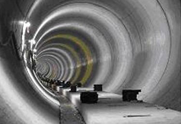
Epping Rail Tunnel construction view
View from Epping end at early construction stage prior to the infrastructure (lighting, rail electric lines, fire protection) fit out. You can see the plinths for the rail line and construction lighting.
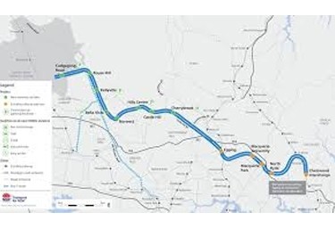
Epping Rail Tunnel map
Epping to Chatswood Rail Tunnel map
Cross City Road Tunnel, Sydney NSW
The Cross City Road tunnel runs between Darling Harbor to Kings Cross under the main Sydney CBD. The tunnel is unique, as the ventilation system runs through a separate tunnel adjacent to the main bores, back to the single ventilation stack in Darling Harbor, the exhaust dispersal patten based on the prevailing winds drops in the middle of the Sydney river due north of darling harbor. This tunnel being located in the Sydney CBD, there was nowhere else to exhaust the gasses too. The water supply are taken from the Sydney CBD near Darling Harbor and Kings Cross, and consists of a grade 1 water supply with 100% capacity pumps at either end. Suitable fire brigade booster facilities were provided at the Darling Harbor and Kings Cross portal areas.
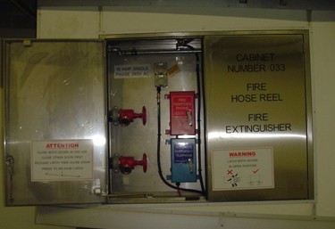
Cross City tunnel emergency cabinet
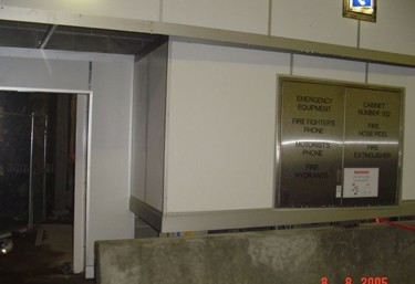
Cross City tunnel - emergency cabinet
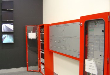
Cross City tunnel - fire panel
Showing the Emergency Equipment (EEC) Cabinet, on the left as the motorist see it, and with the fire brigade section open (usually locked shut), the general public section contains a fire hose reel, fire extinguisher and emergency phone linked directly to the Tunnel Operations Control Room
Cross City Tunnel, showing the Emergency Equipment (EEC) Cabinet adjacent to a cross passage entrance with the doors closed
Cross City Tunnel, view of the fire alarm panel and mimic panel, located in the control room
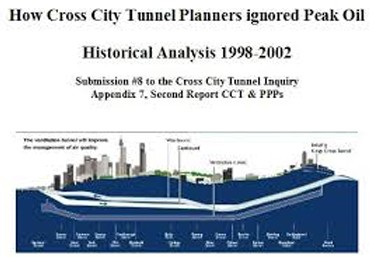
Cross City tunnel side view
Adjacent is a side view of the Cross City Tunnel, also showing the ventilation tunnel under the main tunnels
Cross City tunnel map
Cross City tunnel Map, showing the location of the tunnel.

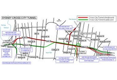
Cross City tunnel tunnel road map
Cross city Tunnel road map, showing all the portals and exists for each direction

Cross City tunnel driver perspective
Cross City tunnel driver perspective
M5 Road Tunnel, Sydney NSW
The M5 Road tunnel, is actually 2 separate tunnels, the M5 Road Tunnel joined by an overland road on a bridge over a swampy area a second smaller tunnel under the Cooks River near the airport.The water supply for the M5 Road Tunnel is taken from both ends of the main M5 tunnel, from a fire water tank and pump complex at both ends of the main M5 Tunnel, in a grade 1 configuration, with a separate singe main feeding the Cooks river tunnel.As with al tunnels there were initial issue of hydrant over pressurization at the lowest levels, this was solved by inserting hydrant valves with orifice plates, to restrict the pressure when the hydrant we running at 5.0 l/sec to what the fire brigade require.
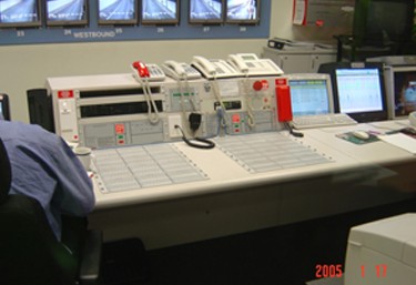
M5 Road tunnel - Control console
M5 road tunnel control console, from an operator's perspective.
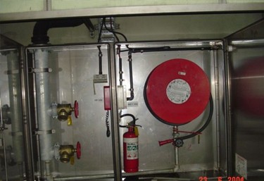
M5 Road tunnel
Showing the Emergency Equipment (EEC) Cabinet (right) with doors open, on the left is the fire brigade section open (usually locked shut) containing feed fire hydrants & emergency intercom phone. On the right the general public section contains a fire hose reel, fire extinguisher and emergency phone linked directly to the Tunnel Operations Control Room Fire Alarm Panel & Emergency Warning Console
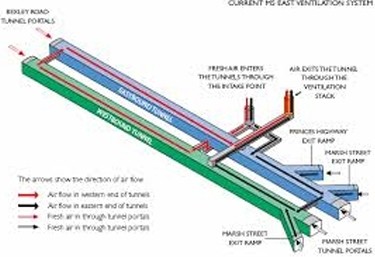
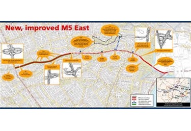
M5 Road tunnel Ventilation Ma
The M5 road tunnel presented issues of how to disperse the ventilation gases, this was achieved via complex method, see the ventilation map adjacent, to a nearby recreation ares (there were many protests by local residences on this matter)
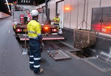
M5 Road tunnel during construction
Construction workers cleaning out the waste pits where roadside rubbish is collected in mesh baskets, where does all this rubbish come from ?? From the people throwing out there rubbish whist driving through the tunnel I summarize?

M5 Road tunnel overheight vehicle damage
There are many warning prior to the tunnel entrance, warning truck driver of being over-height, this is what happens when an over height vehicle enter the tunnel and the damage caused to the vehicle and tunnel roof services
M5 Road tunnel map
M5 Road Tunnel surface map location